460 Harley Knox Blvd
Perris, CA 92571
Tel: 951.277.0757
Fax: 951.277.2757
Email: info@triadmagnetics.com
Website: www.triadmagnetics.com

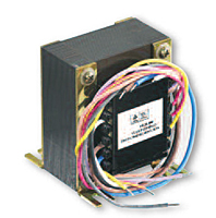
Chassis Mount Leaded World Series™ power transformers from Triad Magnetics set the standard for leaded transformers; with more than 35 models, they are suitable for use in a range of applications and industries.
Constructed with European style split bobbins, Triad’s Chassis Mount Leaded World Series™ power transformers meet all international safety agency standards. The split bobbin construction also reduces interwinding capacitance, which eliminates the requirement of expensive electrostatic shielding, and allows for 3,500 V of isolation between the primary and secondary.
Our Chassis Mount Leaded World Series™ power transformers feature wire leads and are compact, with mounting widths ranging from 2 in to 3 9/16 in. Electrical ratings range between 5 VA and 56.0 VA, and nominal secondary voltages range between 1.3 V and 26.8 V.
To learn more about Triad’s Chassis Mount Leaded World Series™ power transformers, contact us today or view the specification table below.

| Items |
 VPL10-500 Chassis Mount Leaded World Series™ Power Transformers |
 VPL12-400 Chassis Mount Leaded World Series™ Power Transformers |
 VPL14-360 Chassis Mount Leaded World Series™ Power Transformers |
 VPL16-300 Chassis Mount Leaded World Series™ Power Transformers |
 VPL20-250 Chassis Mount Leaded World Series™ Power Transformers |
|||||
| Description |
N/A
Triad International Series transformers are constructed with European style split bobbins to meet International safety agency standards. The split bobbin construction reduces interwinding capacitance and eliminates the need for electrostatic shielding. Available in sizes from 5 VA to 56 VA 115 V / 230 V 50/60 Hz Primary windings; 3,500 V isolation between primary and secondary; designed with 6 mm creepage distance primary to secondary. |
|||||||||
| Click here to check stock >> | N/A | N/A | N/A | N/A | N/A | |||||
| Electrical Rating | N/A 5 V·A | |||||||||
| Secondary Series Connected | N/A 10.0 V0.500 A | N/A 12.6 V0.390 A | N/A 14.0 V0.360 A | N/A 16.0 V0.310 A | N/A 20.0 V0.250 A | |||||
| Transformer Contact Type | N/A Center Tap | |||||||||
| Secondary Parallel Connected | N/A 5.00 V1.000 A | N/A 6.30 V0.780 A | N/A 7.00 V0.710 A | N/A 8.00 V0.620 A | N/A 10.00 V0.500 A | |||||
| Center Tap | N/A N | |||||||||
| Case Type | N/A X | |||||||||
| Height (H) | N/A 1 7/16 in | |||||||||
| Width (W) | N/A 2 3/8 in | |||||||||
| Depth (D) | N/A 1 7/16 in | |||||||||
| Mounting Width | N/A 2 in | |||||||||
| Mounting Depth | N/A | |||||||||
| Primary Voltage | N/A 115 V230 V | |||||||||
| Primary Frequency | N/A 50 Hz60 Hz | |||||||||
| Creepage Distance | N/A 6 mm | |||||||||
| Weight | N/A 0.40 lb | |||||||||
| Technical Notes |
N/A
|
|||||||||
| Note |
N/A
Primary and secondary windings are designed to be connected in Series or Parallel. Windings are not intended to be used independently Class 2/3 UL File: E65390, others TUV only |
|||||||||
| Nominal Secondary Voltage | N/A 5 V10 V | N/A 6.3 V12.6 V | N/A 7 V14 V | N/A 8 V16 V | N/A 10 V20 V | |||||
| Secondary Voltage-Series Connection | N/A | |||||||||
| Secondary Voltage-Parallel Connection | N/A | |||||||||
|
|
||||||||||